
The hole shape is made by drawing a 2D profile them revolving it around the centerline, which in the view below is the on the left side. The 2D shape, in profile, makes up one half of the hole.

I needed nine such holes but not on a regular pattern. It turns out there is a way to duplicate features in SolidWorks but using it is a little confusing - the manual page and tutorial are pretty short. I'm documenting the process here so I can give some tips (and remind myself how to do this a year from now when I probably will have forgotten the whole thing).
The first thing you need to do is to create a coordinate system. This was for me one of the confusing parts. The coordinate system defines an orientation (which direction is X, Y, and Z, including which way is positive and negative) and an origin (what point corresponds to coordinates 0,0,0). There are a few ways to define a coordinate system. For this, I'm setting an origin, Y, and Z. From those the software figures our which way is X.
To begin, I've drawn the 'base' into which all these holes will be extruded:

I started the hole by using the hole wizard, but hole wizard isn't magical. All it does is creates two 2D sketches then revolves the second one around a centerline:
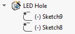
The first sketch does nothing but define the center point of the hole. The second sketch is the 2D hole shape listed above.
Next, what I did was to create a reference point that marks the center of the hole - essentially what this does is to bring the centerpoint of the hole out of the sketch and up to the 3D drawing.

Now I have my base with one hole in it:

The next step is to define a coordinate system. In my case, the origin is the center of the hole. This mean that in my table, the first hole will be at location 0,0 and all the "copies" will be relative to that:

Next I create the table. I did this in excel. By default the units will be in the same units as your document, but you can specify 'in' or 'mm' (or any other SolidWorks unit) if you like:

Finally, create the pattern:

A couple of things to note:
- The coordinate system is placed at the point we created, so that's 0,0 - all the coordinates in the table will be relative to that
- The "Feature" is the hole, created by the hole wizard (then its shape modified by me)
The result is my baseplate with all of the holes replicated at my X,Y locations:

Now don't ask me what it is (it's a secret) - I'll tell you next month!
No comments:
Post a Comment